What’s new in SolidWorks 2012: Magnetic Lines

Just over a year ago, 3DVIA was showing off something called Magnetic Lines.  In 3DVIA, Magnetic Lines are a documentation aid that allows you to quickly line up any type of objects with each other by attaching them to a common line.  Most notibly, Magnetic Lines can be used to quickly align item balloons on assembly drawings.  Many users asked the question, if it is in 3DVIA, why not have it in SolidWorks.  Well, the SolidWorks team took the request seriously.  Within one year, they introduced Magnetic Lines in SolidWorks

Unlike 3DVIA, SolidWorks’ Magnetic Lines only control item balloons.  (SolidWorks has other tools to align annotation notes and drawing views.)  You can add a Magnetic Line to your drawing with the Magnetic Line command from Annotations toolbar or the Annotations tab in the CommandManager.

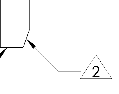
This will enable you to draw a line on your drawing with two points, thus forming a Magnetic Line.  You can drag one end of the Magnetic Line through the center of an existing balloon to attach it to the line.  You can also drag a balloon onto a Magnetic Line.  Magnetic Lines are only visible when the command is active, or when a  balloon is selected. 

Once balloons are attached, they can quickly aligned in any direction by dragging one end of the Magnetic Line.  They can also be moved in unison by dragging the Magnetic Line from the middle.

To detact a balloon from a Magnet Line, click on the balloon to drag it off of the line.  In my opinion, just about everything with this new tool is intuitive and easy!  It is a powerful new drawing aid that makes organizing balloons on assembly drawings much easier.

New inspection symbols added to SolidWorks 2012 symbol library

An unofficial standard has crept into the Drafting field for mechanical drawings.  In an effort to leverage drawings for functions other than defining the specifications for product, many companies are placing Quality Inspection (also known by other names such as Incoming Inspection) instructions on their drawings.  One common method to identify inspection dimensions is to place a “race track” symbol around them.  This is essentially a border with rounded ends.

When I last checked, neither ASME or ISO standards currently support the race track inspection symbol.  This means use of the symbol technically has no meaning unless the drawing has the definition somehow included within it.  This can either be in the form of a reference to a company’s drafting standard or a note within each drawing’s general notes.

If a company chooses to define the symbol in the general notes, they are left with an interesting problem.  How do they describe the symbol so that they can define it.  Although the race track may be easily placed on a dimension in most CAD applications, it is not so easily placed in annotation notes.  They could use a verbose method.

The problem with this?  It doesn’t necessarily get the message across.  What’s a race track border?  Maybe they could say “…DENOTED BY ROUNDED OUTLINE” or “…DENOTED BY OVAL.”  The general problem is the same with any of these options.  The description doesn’t fully communicate what is being defined.

SolidWorks does have a few methods to include a faked symbol in general notes (such as a border around empty spaces, or a sketch block placed under the note).  Now, here’s something you won’t see in the SolidWorks 2012 What’s New document.  With SolidWorks 2012, there is a new heading in Symbol Library called Inspection Symbols.  Depending on company preferences, there are two new symbols that may be included with an annotation note.

Also included in the Inspection Symbol library is a new symbol that may be used for non-dimensional inspection points.

Auxiliary views for those strange angles

I rarely used auxiliary views.  Every once in awhile, parts defy orthogonal projection.  These are when auxiliary views are useful.  In those cases, auxiliary views are generally projected from some perpendicular surface.  But once in awhile, there’s a part that defies even this, having no flat surfaces from which to project.  

In the example below, there is a feature that cuts through a part at an odd angle.  There is no flat surface into which it cuts.  Normally, in SolidWorks, the direct view of this cut could be shown by using the Auxiliary View tool and selecting a perpendicular surface from which a view may be projected.  Here, there is no such flat surface.  SolidWorks does support these kind of oddball scenarios.  

In this example, we are still going to make use of the Auxiliary View tool.

1. Add a side view of the part.

2. Sketch a line onto the view. 

3. Add relations to the sketch line to make it perpendicular to the feature that is to be detailed.


4. Pre-select the line and then chose the Auxiliary View tool from the Drawing toolbar or at Insert pulldown menu>Drawing View>Auxiliary. 

5. A preview will appear attached to the mouse cursor.  Move the cursor in the direction that will be projected and click to place the view.  Depending on the version of SolidWorks, some further adjustment may be necessary to show the view arrow and other details with certain perferences.

Match up projected Break View with its parent view

Break views are common practice for some industries where long components do not fit well on standard sheet sizes at a useful scale.  SOLIDWORKS has a function to break views in the Break tool in the Drawing toolbar.  However, what if there is a projected view of that component that must also have a break?  Do the breaks in each view automatically track with each other (match up)?

Yup, but as with many abilities in SOLIDWORKS, there’s a setting.  This setting allows the user to determine if they want the projected view to always match up with the breaks in the parent view.  This choice is important, as there may be very real purpose to not have breaks in views line up.  For example, the parent and projected views may show details at different locations along the length of the component.

Unaligned break view


However, if the user wishes the parent and projected views to break at the same locations, the setting is located for the projected view in its PropertyManager>More Properties… button>Align Breaks with Parent check box.


End result in this example after a quick rebuilt (CTRL-B):

Break View UPDATE!

Newer versions of SOLIDWORKS automatically set Align breaks with parent property as checked. If you wish to have a projected view with different break alignment from its parent, you’ll have to uncheck this setting.

New in SolidWorks 2012: User interface improvements

This is the first in a series of articles that will cover *some* highlights of new functions added in SolidWorks 2012.  Just as a matter of a reminder, I am an employee of Dassault Systemes.  However, what I’m doing here is talking about improvements that interest me.  User Interface isn’t the most exciting topic to start with.  However, these are good improvements (a couple of which are a long time coming).

Recent Documents

In a recent release, Recent Documents window (accessed via File pulldown menu>Browse Recent Documents… or by pressing the letter R on out-of-the-box installs) was drastically improved with a more accessible interface.  There’s been several minor improvements in SolidWorks 2012.  The one that impressed me the most is the addition of a pin that allows you to pin a document onto the Recent Documents window.   No matter how many other documents come and go, your pinned document will remain on the Recent Documents list until you unpin it.  No matter where you originally pin your document in Recent Documents window, pinned documents automatically reposition themselves to the top-most/left-most available position to allow for best discoverability.

Additionally, the pin function is also available on the list of recent documents in the File pulldown menu itself.  Pinned documents here are the same as in the Recent Documents window. 


Search Commands

Search Commands is a new tool that allows you to nearly instantly type in the name of a command in order to find and run it.  The concept is kind of a throwback to the old days with command line driven CAD.  However, the implementation in SolidWorks provides helpful results that navigate through the CommandManager as choose your command.

Search Commands may be activated in a number of ways, but the quickest out-of-the-box method is the S-Key.  Yup, the S-Key has just been made more powerful with the added function of activating Search Commands tool.  S-Key still brings up the Shortcut bar.  The difference is that now you can just start typing the name of the command for which you are searching.

Additionally, you can assign shortcuts to Search Commands so that tools can now be run with a series of keystrokes instead of being limited to single keystrokes or CTRL/SHIFT/ALT combinations.

Spanning and Fitting to Displays (real multiple monitor support is finally here!)

You can now control how SolidWorks displays itself and individual documents across multiple monitors in a useful manner.   The new span option works with single monitors just as well too.


With two monitors, this option knows how to place two documents so that each on fills one of the two screens.  It even knows how to handle two monitors of difference sizes and resolutions where the SolidWorks window may not fill both equally.  Spanning Displays is a big useability improvement for those of us that frequently need more than one document open.

Controlling how flag notes are attached to leaders (part 2)

This entry is part 2 of 2 in the series Controlling how flag notes are attached to leaders

I’m finally getting around to part 2 of my article Controlling how flag notes are attached to leaders.  Sorry for the long delay.  There’s been a lot going on IRL.  Also, for a very brief .001 second, I thought it might be funny to just do a bunch of part 1’s and never get around to doing part 2’s or 3’s.  Unfortunately, that would only be funny to me, so it wouldn’t really be funny at all. 

Add flag notes to drawings using annotation borders

In addition to flag note symbols mentioned in part 1 of this article, another way to create flag notes is with the use of annotation borders.  Depending on the results you want, there’s two ways to add borders.  The method is the same, but selection choices make for slightly different results.

1. Create an annotation note with a leader.

2. Type in the number of the flag note.

3. While still editing the annotation, highlight the number (either using SHIFT and LEFT ARROW or by selecting with the mouse)

4. While remaining in the edit mode (with the text highlighted), click on the Border drop down box in the PropertyManager.  Choose the required shape.


5. Choose OK and this will be your result.  Note the gap between the leader shoulder and the flag note (image below).  This is similar to the result when using a flag note symbol from the Symbol Library.  For triangles, this border method produces an equilateral triangle, where the Symbol Library is an isosceles triangle.

Flag note with touching leader (no gap)

Some people may prefer a flag note that touches the shoulder of the leader.  This is my personal preference too.  It follows the same look and feel as balloons and other symbols.  To achieve this style, follow steps 1 and 2 above, then continue with these steps below.

3. Exit the edit mode.  You should see a leader with just a number.

4. Select the leader note as one entity (LMB click anywhere on the leader note; shoulder, arrow, text, doesn’t matter).

5.  With the note selected, click on the Border drop down box in the PropertyManager.  Choose the required shape.


6. Choose OK and this will be your result.  Note the leader shoulder connects with the flag note (no gap).

I hope this How-to (or is this a Tips and Tricks?) helps!